Introduction
Like classical column buckling theory, the buckling of columns under eccentric (offset) loads is also a topic of unique complexity. It is unique in that the analysis leads to nonlinear dependences of beam deflections and stresses on the applied load. As shown in the figure, a load, \(P\), is eccentric when its line of action is offset a distance, \(e\), from the column. This produces a bending moment equal to \(P*e\) that exists in addition to the usual deflection-related moment in the classical theory.Curiously, the mechanics of eccentric column buckling can be considered more straight-forward than those of the classical theory. For example, unlike classical column buckling, failure here can indeed be related to the material's yield strength. In fact, it will be shown that under eccentric loading conditions, failure will always occur due to stresses exceeding the material's yield strength before the load reaches its so-called critical value, \(P_{cr}\).
Analytical Solution - Both Ends Pinned
Analysis of the buckling of eccentrically loaded columns begins just as that of classical Euler Buckling Theory, with the beam bending equation.\[ E \, I \, y'' = M \]
However, this time the bending moment is slightly more complex. It is now \(M = -P \, (y + e)\), where \(P\) is the compressive load, \(y\) is the column deflection, and \(e\) is the offset distance of the load relative to the vertical portion of the column, the eccentricity.
Inserting this expression for \(M\) in the above differential equation produces
\[ E \, I \, y'' + P \, y = -P \, e \]
which has the following general solution
\[ y = A \sin \left( \sqrt{{P \over E \, I}} \; x \right) + B \cos \left( \sqrt{{P \over E \, I}} \; x \right) - e \]
where \(A\) and \(B\) are constants determined from the boundary conditions.
The boundary conditions are \(y = 0\) at \(x = 0\) and \(x = L\), corresponding to both ends being pinned.
The first boundary condition, \(y = 0\) at \(x = 0\), leads to the conclusion that \(B = e\). And this gives
\[ y = A \sin \left( \sqrt{{P \over E \, I}} \; x \right) + e \left[ \cos \left( \sqrt{{P \over E \, I}} \; x \right) - 1 \right] \]
The second boundary condition, ( \(y = 0\) at \(x = L\) ), gives
\[ A = e \, \tan \left( \sqrt{{P \over E \, I}} \; {L \over 2} \right) \]
And the complete solution to the differential equation is
\[ y = e \, \left[ \tan \left( \sqrt{{P \over E \, I}} \; {L \over 2} \right) \sin \left( \sqrt{{P \over E \, I}} \; x \right) + \cos \left( \sqrt{{P \over E \, I}} \; x \right) - 1 \right] \]
Interesting Observations
Equally interesting is the fact that the dependence on eccentricity, \(e\), is linear even while the dependence on load is not. In fact, the deflection of every portion of the column is directly proportional to the eccentricity. Note that the equation reduces to the scenario of classical column buckling as \(e\) goes to zero because it predicts \(y = 0\) everywhere even in the presence of the load.
Returning to the case of nonzero eccentricity. Yet another fascinating property of the analytical solution above is its dependence on the tangent function. Recall that the tangent function goes to infinity as its argument approaches \(\pi/2\). Therefore, the solution is telling us that the column deflections become infinite whenever
\[ \sqrt{ P \over E \, I } {L \over 2} = {\pi \over 2} \]
Solving this equation for \(P\) gives the following result, which is remarkable because it is exactly the buckling solution for classical noneccentrically loaded columns.
\[ P_{cr} = {\pi^2 \, E \, I \over L^2} \]
Furthermore, it is independent of the eccentricity, \(e\). This is completely counter-intuitive. All engineering intuition presumes (strongly!) that the buckling load should decrease as the eccentricity increases. We will resolve this next... and engineering intuition will be satisfied.
A Subtlety Concerning the Eccentric Loading
I had initially used these two images (at right) on the top of this page, but recently realized that they are incorrect. The key issue is that these two sketches do not include a mirror-image \(P_{external}\) eccentrically located and pushing upward on the bottom of the column.The consequence of this omission is that it would be necessary to have a lateral reaction force present at the top of the column where it is pinned (its upper left corner) in order to maintain equilibrium. This becomes evident if moments are calculated about the base of the column. A lateral force, pushing left at the top, is necessary to counteract the fact that \(P_{external}\) exerts a clockwise moment about the base.
In contrast, note that lateral forces are no longer necessary in the new sketch at the top of this page because of the presence of the two equal and opposite \(P_{external}\) forces.
Stresses
\[ \sigma = {P \over A} + {M \, \text{y} \over I} \]
where \({P/A}\) is the stress due to the compressive load, and \(M\,\text{y}/I\) is the stress due to bending. Note that \(\text{y}\) here is not the column deflection. It represents the distance from the column's neutral axis. Note also that sign conventions are being completely ignored here because everything is being treated as a positive value, when in fact, the stress is clearly compressive. Even the applied load is being taken as a positive value. This is OK. Simply interpret the stress as an absolute value.
The question is, "What is the maximum compressive stress in the column?" This is found by inserting the conditions that maximize the effects of bending. The maximum bending stress occurs at a point in the cross-section farthest from the neutral axis, i.e., \(\text{y} = c\). Second, it occurs where the bending moment is a maximum along the column's length. In other words
\[ \sigma_{max} = {P \over A} + {M_{max} \, c \over I} \]
Recall from above that \(M = P \, (y + e)\) where \(y\) now represents the beam/column deflection (and once again, negative signs are being ignored). So the maximum bending moment, \(M_{max}\) corresponds to the maximum beam deflection.
\[ M_{max} = P \, (y_{max} + e) \]
So \(y_{max}\) is needed. This occurs at \(x = L/2\) on the beam. Evaluating the column deflection at \(L/2\) gives
\[ \begin{eqnarray} y_{max} & = & e \, \left[ \tan \left( \sqrt{{P \over E \, I}} \; {L \over 2} \right) \sin \left( \sqrt{{P \over E \, I}} \; {L \over 2} \right) + \cos \left( \sqrt{{P \over E \, I}} \; {L \over 2} \right) - 1 \right] \\ \\ \\ & = & e \, \left[ \sec \left( \sqrt{{P \over E \, I}} \; {L \over 2} \right) - 1 \right] \end{eqnarray} \]
Recall that \(\sec(x) = 1 / \cos(x)\).
\[ \begin{eqnarray} \sigma_{max} & = & {P \over A} + {M_{max} \, c \over I} \\ \\ & = & {P \over A} + {P \left\{ e \left[ \sec \left( \sqrt{{P \over E \, I}} \; {L \over 2} \right) -1 \right] + e \right\} c \over I} \\ \\ & = & P \, \left[ {1 \over A} + {e \, c \over I} \sec \left( \sqrt{{P \over E \, I}} \; {L \over 2} \right) \right] \end{eqnarray} \]
Like the tangent function, the secant function also goes to infinity as its argument approaches \(\pi/2\). The result is that the predicted stress also approaches infinity. This leads to a new column failure criterion, namely, the column will fail when the stress equals the material's yield stress: \(\sigma_{max} = \sigma_{yield}\).
\[ \sigma_{max} = P \, \left[ {1 \over A} + {e \, c \over I} \sec \left( {\pi \over 2} \sqrt{P \over P_{cr}} \, \right) \right] \]
where \(P_{cr} = \pi^2\,E\,I\,/\,L^2\). This reveals that \(P_{cr}\) in eccentrically loaded columns is only an academic landmark. The column will actually fail when \(\sigma_{max} = \sigma_{yield}\), and this will always occur at a load less than \(P_{cr}\).
Eccentric Buckling Example
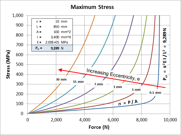
The graph here shows the predicted stress in an 850 mm long steel bar (E = 200,000 MPa) with cross-sectional area of 100 mm2. The stress is plotted against load for a series of different eccentricities.The graph reveals several important properties of eccentric column buckling. The story begins with the lowest (blue) curve for the near-zero eccentricity of 0.1 mm. This curve approaches the theoretical limit where the stress is simply \(P / A\) until it suddenly goes to infinity at \(P = P_{cr}\). Of course, any object will yield, and soon fail, when its stress goes to infinity, and this is consistent with the noneccentric buckling theory in which the column fails at \(P = P_{cr}\).
Second, the load at which the stress grows rapidly, decreases with increasing offset, \(e\). Therefore any such eccentrically loaded column will fail before \(P\) reaches \(P_{cr}\) because the stress in it will, at some point, exceed its yield strength. This is the property of eccentrically loaded columns that satisfies intuition even though \(P_{cr}\) is independent of \(e\).
Dimensionless Parameters
The equation for stress can be cast in a nondimensional form, permitting all solutions to be plotted as a series of dimensionless parameters in a single graph. This is accomplished by first returning to the following equation.\[ \sigma_{max} = P \, \left[ {1 \over A} + {e \, c \over I} \sec \left( {\pi \over 2} \sqrt{P \over P_{cr}} \, \right) \right] \]
Next, factor area, \(A\), out of the bracketed term
\[ \sigma_{max} = {P \over A} \, \left[ 1 + {e \, c \, A \over I} \sec \left( {\pi \over 2} \sqrt{P \over P_{cr}} \, \right) \right] \]
and move it to the left hand side.
\[ \sigma_{max} \, A = P \, \left[ 1 + {e \, c \, A \over I} \sec \left( {\pi \over 2} \sqrt{P \over P_{cr}} \, \right) \right] \]
Finally, divide both sides by \(P_{cr}\).
\[ {\sigma_{max} \, A \over P_{cr}} = \left( {P \over P_{cr}} \right) \, \left[ 1 + \left( {e \, c \, A \over I} \right) \sec \left( {\pi \over 2} \sqrt{P \over P_{cr}} \, \right) \right] \]
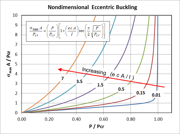
The equation is now nondimensional. It contains several dimensionless terms: \( ( \sigma_{max} \, A / P_{cr} ) \), \( ( e \, c \, A / I ) \), and \( ( P / P_{cr} ) \).
All solutions of the equation can now be plotted as a series of master-curves on a single graph.
Dimensionless Parameter Calculation Example
Assume we have a 100 in long bar made of aluminum having \(E = 10\text{E}6\) psi and yield strength of \(\sigma_{yield} = \) 65,000 psi. If the bar has \(c = 0.5\,\text{in}\), \(A = 1\,\text{in}^2\), and \(I = 1\,\text{in}^4\), then \(P_{cr}\) is\[ P_{cr} \quad = \quad {\pi^2 \, E \, I \over L^2} \quad = \quad {\pi^2 * 10\text{E}6\,\text{psi} * 1\,\text{in}^4 \over (100\,\text{in})^2} \quad = \quad 9,870\,\text{lbf} \]
But! Now assume that the load is offset 3 in from the column axis. Now the column will fail at a lower load than \(P_{cr}\) because the stress in the column will reach the aluminum's yield strength. To determine how much lower, we first need to compute
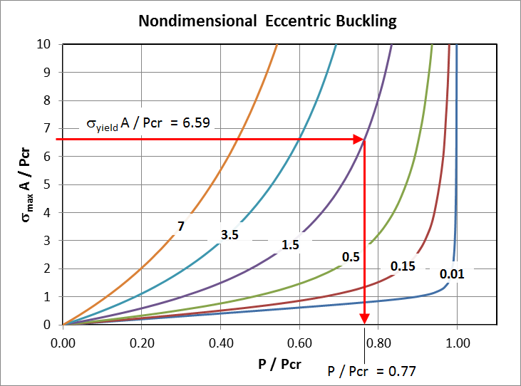
\[ {\sigma_{yield} \, A \over P_{cr}} \quad = \quad {65,000\,\text{psi} * 1\,\text{in}^2 \over 9,870\,\text{lbf}} \quad = \quad 6.59 \]
And we also need to calculate
\[ {e \, c \, A \over I} \quad = \quad {3\,\text{in} * 0.5\,\text{in} * 1\,\text{in}^2 \over 1\,\text{in}^4} \quad = \quad 1.5 \]
So all we need to do is start on the y-axis at a value of 6.59 and march across until we intercept the curve labeled "1.5" for \(ecA/I\). We then turn down and find that we intercept the x-axis at \(P / P_{cr} = 0.77\). The stress in the bar will therefore reach \(\sigma_{yield}\) at
\[ P \quad = \quad 0.77 \, * \, 9,870\,\text{lbf} \quad = \quad 7,600\,\text{lbf} \]
It would be incorrect to assume that the bar can withstand 9,870 lbf compressive load if that load is offset 3 in from the bar's axis. Instead, the bar will start to yield at a load of only 7,600 lbf.
Ratio of Stresses
The dimensionless term containing stress merits additional comment. Rewriting it as\[ {\sigma_{max} \over P_{cr} / A} \]
permits the denominator to be interpreted as the critical compressive stress that would cause the column to buckle (when \(e = 0\)). Call this \(\sigma_{cr}\).
\[ {P_{cr} \over A} = \sigma_{cr} \]
The dimensionless stress term now becomes \(\sigma_{max} / \sigma_{cr}\). As in the example above, it is common to equate the maximum stress in a column to the material's yield strength, \(\sigma_{yield}\), in order to back-solve for \(P\), the maximum load the column can support (not \(P_{cr}\)). This leads to the ratio
\[ {\sigma_{yield} \over \sigma_{cr}} \]
This stress ratio, \(\sigma_{yield} / \sigma_{cr}\), is the focus of this discussion because of its unique interpretation. Specifically, it reflects the ratio of (i) the maximum possible load a column could carry before it yields if no buckling were to take place, to (ii) the maximum load it could actually carry when limited by buckling considerations (again, under the condition that \(e = 0\)). The higher this ratio, the more severe the buckling limitation is. For example, in the example above, it was equal to 6.59. If buckling could be prevented (perhaps through the use of lateral supports), then the column could support 6.59 times more load before it yields.


